130 XE Upgrades

Not too long ago I was wanting something new to explore for my Atari 130XE. There is an Atari freind in Poland who goes by “Lotharek" who makes some very nice hardware. I bought a NetUSBee (ethernet and USB from the cartridge port) from him for my STe, and I really like it. It is much more compact than my old EtherNEC boxes, and recently someone finally wrote working drivers for USB storage. It is so nice to be able to transfer files with a USB stick from a Mac, PC or another Atari system with USB. Lotharek’s hardware is first class!
I started out on my quest to improve the 130XE by purchasing the SIDE2 cart. I have used a MyIDE cart for years, but that cart required an IDE adapter along with a compact flash card. It served me very well, but I was curious to see if the SIDE2 would be an improvement. I always learn new things when I try out new hardware. The SIDE2 doesn’t need the IDE adapter and includes Spartadox X and a real time clock.
I found that for my purposes, the SIDE2 was not better than the MyIDE (at first), because I like to use AtariWriter Plus, and it was not compatible with the SIDE2 cart because the Spartados in the cart uses the same memory area. I discovered if I were to install the Ultimate 1 MB upgrade, then things should work.
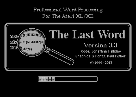
When I started to check out the Ultimate 1 MB upgrade, I found out there is an excellent word processor, “The Last Word” by Jonathan Halliday that supports the VBXE upgrade. All this really got me interested, so I decided to make this a major upgrade project. After all, it takes things awhile to get here from Poland, so I thought it would be fun to purchase most of the available upgrades in one order.
While I was waiting for my order, I looked for a good upgrade candidate 130XE on eBay. I wanted to keep my 130XE in stock condition. It is has been a good old “freind”, and I didn’t even want to think about drilling any holes in the case or anything like that. It is possible to do the upgrades without “hurting” the machine, but I was planning some slight case mods. I also wanted to keep a machine on hand do use during the upgrades. It turned out that the upgrade machine was never really “down” during the process, so that was not a concern. I found another nice, working 130XE.
I ordered the Ultimate 1 MB upgrade, the VBXE, the Simple Stereo (dual Pokey), and the P Covox (another sound upgrade).
Everything was easy to install (you need basic soldering skills, and it does not hurt to have some electronics knowledge). It is good to plan ahead and make sure you have the correct sockets for the IC chips and a Dupont connector kit with the various pin connectors you will need. I used ribbon cable wires to make the various connections and it worked very well.
Some great resources for planning include atari8.co.uk and the AtariAge 8-bit Computer forum. I viewed every YouTube video I could find about these installations before my order arrived. It really saved a lot of the guess work.
Everything went as I planned until I got to the P Covox. In order to install that upgrade, I had to bend the pins on the Simple Stereo upgrade upward at a right angle because the two upgrades are right next to each other (PIA and POKEY chips). I bent the pins up and used some insulating tape to make sure the pins on the Simple Stereo were not touching the pins on the PIA chip for the P Covox.
Also, I had no idea where the base address for the P Covox should be set. I read somewhere that the default base address may conflict with something??? I do not know what. I ended up using the default base address, and I have not had any issues with that. Also, the instructions state that it is not recommended to use the same outputs that are used to send the sound to the speakers for the Simple Stereo upgrade. I wasn’t about to drill more holes for another set of RCA outputs, so I just decided to run a wire with a 3.5 mm stereo connector attached through the hole that is already there for the PBI connector (I’m not actually using a “real” PBI device, so that port is not needed). The input to my speakers is 3.5 mm stereo (like a headphone connector) and there are two inputs, so it worked out nicely. If I want to get slick about it later, I may install a bluetooth transmitter inside the case connected to the P Covox outputs, but I doubt I’ll ever go to that trouble.

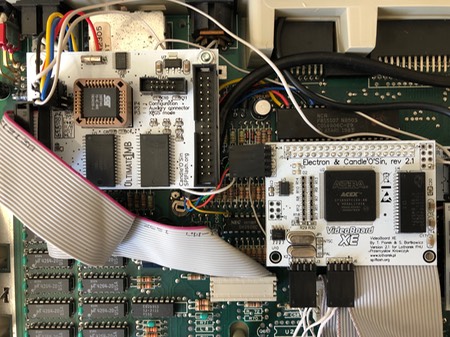
In the photo above you see my only screw up. I mounted the RGB DB9 jack too low. The screw would meet with the motherboard, so I could not put a screw in the bottom. I was not happy about that! One of those measure twice, cut once moments. Everything needs to be measured with the motherboard in the case!!!
I thought that the video output for the VBXE was going to be tricky, but it was actually very easy. Others are installing an RGB connector (I think it is 13 pins) like you find on an Atari ST, which is pretty slick, but I had no option for an RGB monitor and wanted to use a nice LED VGA monitor. I am actually using an LG TV, so I have a DB9 connector on the back of the 130XE case to which I connect a scan converter (RGB to VGA) and then a small box convert VGA to HDMI. This sounds crazy, but I tried a nice VGA monitor, and I actually get better quality with the LG TV, and I can connect the original Atari output to the composite on the TV and switch back and forth from original output to VBXE if I wish.

It is important to work slowly and carefully and double check everything as you go. Make sure you don’t skip steps in the instructions.
This was a very fun project, and considering all the chips I removed to install sockets, it was quite easy. I was amazed and glad that I did not break anything, and that everything worked when I turned on the power switch!
I think the only upgrade I did not install was the Rapidus. I just didn’t see a need for the 130XE to run faster, and truthfully I don’t think much software will be developed that would need such a thing.
I did pre-order the BIGGUS DICKUS Sio2sd. I don’t have an Sio2sd, and it looks cool and the name is funny. After all, this is mostly about having a little fun after some very long days at work!
STBook replacement - Pi-top with BeePi!
In October of 2015 I sent my STBook to a friend over the pond for repair. This friend was awesome for a long time and very helpful. He is (or was?) a genius with Atari hardware. He had worked on my STBook previously and sent it right back in working order with a new battery and charger and the screen repaired. When the screen failed again rather quickly, I sent it to him again. This time around it has been over three years, and I never hear from him anymore. I don’t know what happened to him. All efforts to contact him have received no reply. I hope that he is okay and will someday return my computer. I have a pretty large investment in that very rare STBook. It is a very unfortunate situation. You can see some of what happened by starting here and browsing backward through the blog posts.
Recently, I started thinking about what I might be able to do to “replace” my STBook. I’m not very excited about using emulators. I prefer to work with the “real” Atari hardware, but where are you going to find another STBook?? I started to think about running an ARANYM setup on a laptop. ARANYM is virtual machine software, and it amazing what it can do. Enter the Pi-Top and BeePi!
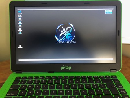
I discovered the Pi-top laptop. As an electronics hobbyist, I’m a big fan of the Raspberry Pi computer and other small, single-board computers like the Arduino. The Pi-Top is an inexpensive, 3D printed educational laptop. You simply add the Raspberry Pi and you have a complete laptop with a sliding keyboard and trackpad enabling you to open it right up to get to the Raspberry Pi and add “hats” to the internal sliding modular rail. The image below shows the pi-top connection bridge on top of the Raspberry Pi, and the Pi-top pulse (speaker, mic and LED array) on the right.

I noticed on Atari-Forum that Philippe had created some very slick distributions of ARANYM and HATARI with a lot of Atari software and tools and a Mint OS. Theses distributions are BeeKey and BeePi for PCs and the Raspberry Pi, respectively and MacAranym for the Mac. I got involved in BETA testing of BeePi with my Pi-top. Soon, Philippe released BeePi 1.0. Since this distribution is based on Raspbian Stretch lite, it enabled me to interact with my Pi-top devices, specifically the Pi-top pulse (speaker, mic and LED array). There are several nice example python scripts for the Pi-top pulse to check out on Github.
BeePi is truly amazing! The distribution comes with everything you need right out of the “box." There is even a simple YouTube Tutorial.
The screen you see above is somewhat customized for my purposes with the Pi-Top. In this version of BeePi when using the Pi-Top, make sure you stick with the default screen resolution for the best results. At this time the native screen size (1920X1080) did not work with the BeePi screen settings tool (for me anyway). If you want to make use of more screen area, use the ARANYM setup dialog (fn+Altgr+F12) to set the video. I had the best results using Fixed Size/Custom Width: 1820 Height: 980.
To use the various Pi-Top devices and software tools, you need to SSH to BeePi at the terminal (SSH root@beepi) and
apt update
apt upgrade
apt install pt-device-manager
shutdown (Halt System)
When you start up the Pi-Top if you have a speaker or a Pi-Top pulse installed you should hear the cool BeePi startup sound when the desktop loads!
You can also go to github and look for all the cool examples for the Pi-top pulse. I tried all of them, and they all worked from the BeePi terminal with no problem at all. The battery gauge app for the pulse is especially useful.
The one thing that is a little frustrating with any Atari is that web browsing can be quite slow. That is still the case when running Netsurf with BeePi on the Pi-top. My solution was to install the Chromium Browser on the host side (Raspbian Stretch Lite).
I followed the instructions here. This did not setup the Chromium Browser in kiosk mode as I expected, but it did give me a minimal desktop with the terminal and the Chromium Browser, which is exactly what I wanted. I can go to “Tools” “Quit to Host” in BeePi, log in at Bash, type the “startx” command and then launch Chromium. I haven’t found any limitations so far using this browser. One important detail is that you will need to add a sudo user to run chrome properly.
adduser (username)
follow the prompts
usermod -aG sudo (username)

When you are ready to go back to BeePi, just type “reboot” in the terminal, and you will boot back to the BeePi OS.
I want to thank Philippe for his outstanding work with BeePi! I think it would have taken years for me to properly configure ARANYM, Mint and Teradesk on top of the Pi-Top OS. I am a fairly experienced Atari user, and I have a nice configuration of Mint and Teradesk on my Falcon, but there is no way I could have come up with anything nearly as nice and complete as this. It is so well done! THANK YOU PHILIPPE!!!!
Swapped Falcon Motherboards
Recently I had a problem with my ETHERNAT. Networking stopped functioning (USB is still working). I was able to obtain a SVETHLANA from NATURE (These guys have always been so kind and helpful over the years!).
In the process, I decided I would swap my Falcon motherboard with one from the “new” Falcon that I bought. My original Falcon had a blown cartridge port fuse that I had jumpered, and it always had the “reset delay” problem with the CT60 (I had to push reset several times to get it to boot). I had tried several “fixes” for the reset delay problem, but I was never able to solve the problem. The board had several clock patches applied and removed over the years and had the audio mods for the analog inputs and outputs. The “new” board was clean with no modifications.
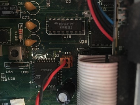
Once I got the “new” board swapped into my Wizztronics Falcon Rack, I only had to make one little mod to get SCSI working properly (my “old” board also had this mod):
The “new” board does not have the “reset delay” issue. So far, everything including the SVETHLANA is working great. I still need to do some “acid testing” with Cubase Audio Falcon. It has always been quite sensitive, especially where writing to SCSI is concerned. Minimal tests have worked so far. I have had some minor issues that I believe may be related to Supervidel timing (I need to experiment with the firmware and timing versions).
I’m hoping to add some YouTube video of the current status of my studio soon. I’m not very good with Video editing, so it takes me some time to get interested in doing it, and more time to actually do it!
So far my “old” Falcon is not booting without the CT60. I suspect that is because it has all the wiring added to “boost” the motherboard, and without the CT60 attached something is not right. I’m trying to get ahold of a CT60e, but I haven’t heard back on that as of yet. Things can sometimes take forever in the “Atari World!”
New Stacy Display
My STBook has been out for repairs for quite some time, so I started thinking about making some improvements to my Stacy. The joy of the STbook is that it is truly small and portable, where the Stacy is more of a “luggable” computer. The big problem with the STBook is the RAM limitation. Less than 1 MB available. My Stacy is a Stacy 2, but it has been upgraded to 4 MB of RAM.
My Stacy had two problems that I wanted to address. The first was that the display was failing, and was also very dim. There was a vertical line coming down from the top of the display, and the bottom of the display would sometimes “go crazy.” It had an open circuit somewhere. If I would squeeze near the speaker it would clear up. Secondly, I wanted to increase the storage capacity. It had a 40 MB hard drive.
Note that you can click on the photos in my blog to expand to a larger image.
If you try any of this, it is at your own risk!


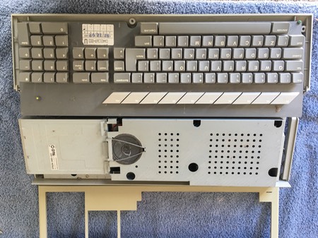
I did some searching on the web, and found the part number for the Epson LCD display. It is an Epson P300031800 (the number printed on the actual circuit board. This is a photo of the display I removed from my Stacy:

Note the white sticker at the top right hand corner. I learned that this must be the part number for the version needed to be the “exact fit” for the Stacy: ECM-A0443. I did not know this when I started searching for the part. I did some searching on eBay and found an Epson P300031800 “Industrial” display in China. It was listed as new, so I ordered it. It took 18 days to arrive. I wondered if it would be the right item, and if it would actually work. There were three differences I noticed, the first being that white sticker with the part number:

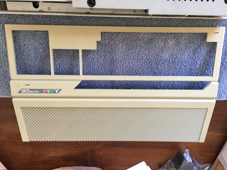
The new display was an Epson EG-8007B-HS-1, but it still had the same part number etched on the circuit board: Epson P300031800. The second difference was the mounting frame. Here is the frame from my Stacy:

Here is the frame from the new display:

You will notice that the mounting locations differ. It was no problem. You just bend the little “ears” holding in the display and swap it out.
The second difference was the power connector. This is the power connector for the original Stacy display:


This is the power connector for the new display:

This was also no problem. I just removed the black connector from the blue and white display power wires and soldered the two wires to the solder pads on the new display. Sorry, I neglected to take a photo with the wires soldered on.
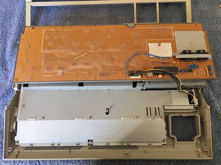
A third problem was the ribbon cable. On the original Stacy display the print and contacts were facing upward. On the new display they were facing downward. I neglected to take photos of this part, but I will be adding some new photos here when I can. It was necessary to move the plastic insulator at the contact end of the ribbon cable on the new display to the other side, so that the contacts were on the correct side for the black display connector on the Stacy. The picture below is the original board, but I have circled the part I changed in yellow:

Now, let’s go back to the beginning. I found this website very helpful in the disassembly of the stacy: http://gtello.pagesperso-orange.fr/stacy_e.htm
It is so important to know about the screws behind the Stacy label on the front of the display!


Start by removing these screws, then the back cover of the display will snap away by gently prying with a flat screwdriver. There are small catches around the cover that hold it on:

When you have the back removed, you will see the display shielding. I found the inside of mine had some notes about a previous display repair. The yellow sticky was about the power wire polarity, and the “sharpie” writing was about a hinge repair.
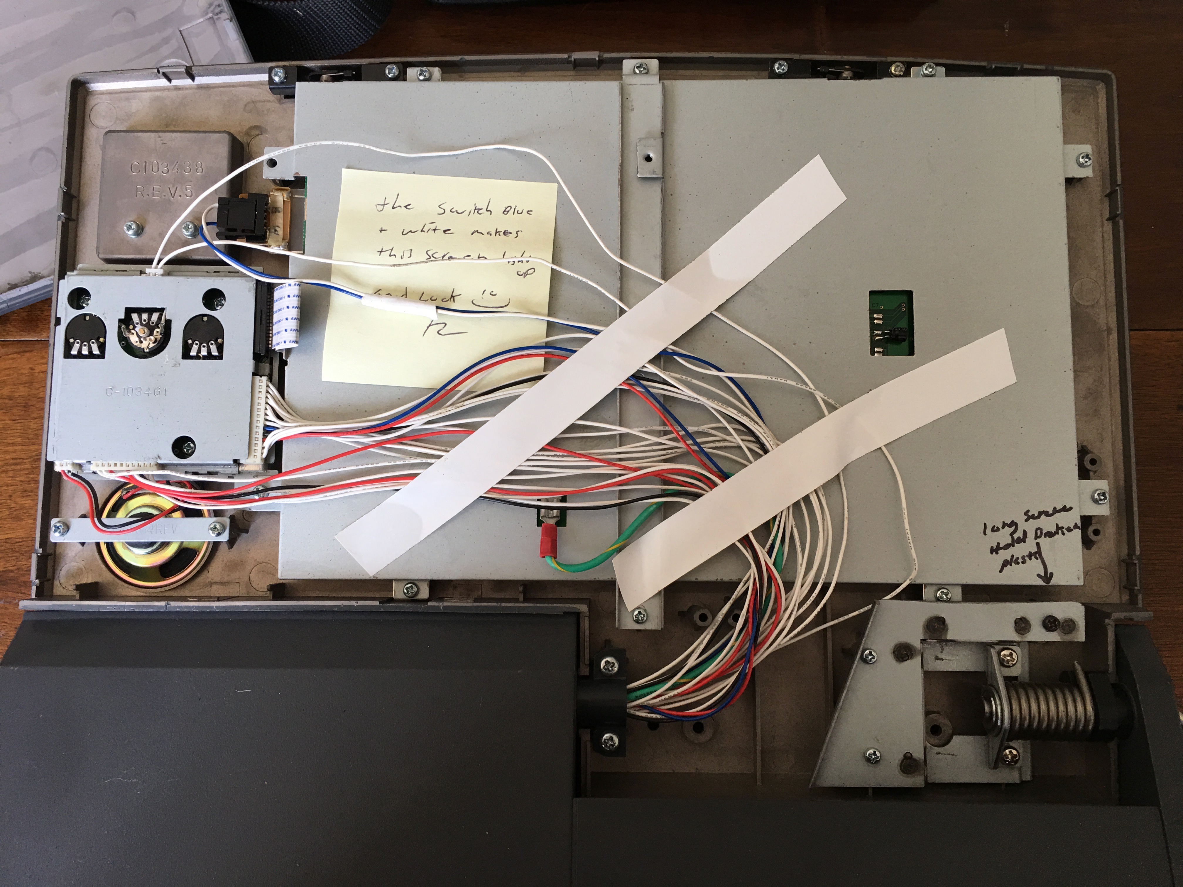
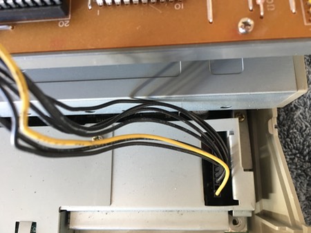
I doubt that the display wiring condition is stock! To remove the display, just remove all the phillips screws holding the shielding, disconnect the black connector for the power, and the ribbon cable for the display data. The connector for the ribbon cable has the typical “slip lock” that you can pull open gently and it will release the ribbon cable. Do not force it out. Make sure the lock is open and it will slide right out. Remove the green grounding wire from the shielding.
Ribbon cable:

Grounding wire:

Display with shielding removed, showing ribbon cable connection and power connection:

Once you have the display removed, just reverse the process to install a new display. My result was quite impressive (at least to me!). Here is before:
Here is after:

I never would have dreamed a Stacy display could be so bright in the daylight! I was right by a window with the sun coming in through a curtain. Here are a couple of examples with less light:


I am very happy with the brightness and clarity of the new display. The display is not perfect. It has a few flaws in the back light material as you can see here (the black spots):

This does not bother me, as the display is so bright and clear, and the black spots are in the background of the display and not the foreground where the text and graphics are displayed. I would also note that the new display has more of a reflective finish, where the original was more of a matt finish.
While I was at it, I replaced the 40 MB hard drive with a 700 MB hard drive (Quantum ProDrive Lighting 730S). I’ll write with the details of disassembly of the bottom case in my next post. That is the difficult part. The screen was actually quite easy.
New Stacy Screen?
Since my STBook is out for repairs, I pulled out my Stacy to get it ready for some projects where I will need portability. It has been sitting for quite awhile, and when I booted it up I noticed that the bottom of the screen is going out. If I “squeeze” the display in the area of the speaker, the screen will come back. My Stacy has always had a vertical line coming down from the top of the display about 1.5 inches long, so I have wanted to repair or replace the screen. I started doing a little research to see if a replacement LCD may be available, before I try to repair the existing display. I found the exact Epson part numbered display on eBay from a few sellers in China. I have ordered one of those from the seller who had the least negative feedback. I also ordered a display from a US supplier. That one was very inexpensive, and has the right size and specifications, but a different part number.
Once the new display with the correct part number arrives, I’ll start the project and take photos of everything. I know that the Stacy is difficult to disassemble, so I am going to take it very slowly and document everything in my blog.
I am very curious to see if I will actually receive a new, working Stacy display or not. Hopefully it will be nice and bright in comparison with the current display.
I will also be replacing clock battery, and should probably also upgrade the hard drive. It already has 4 MB of RAM installed. I’m not sure if I want to mess with the TOS version or not. It would be nice to have 2.06 installed if there are no issues with a Stacy. (Update) I just read that 2.06 needs a patch for the Shadow chip on the Stacy.
New Falcon Arrival
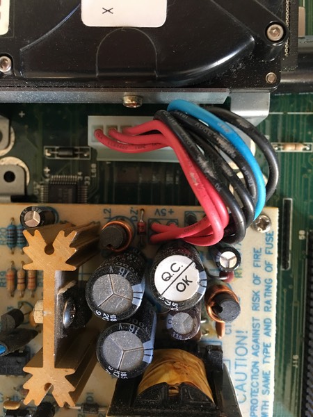
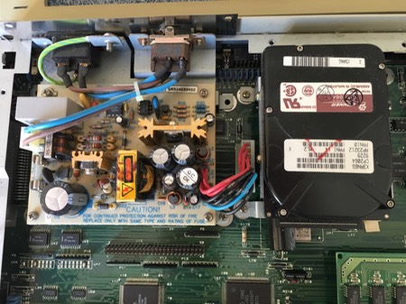
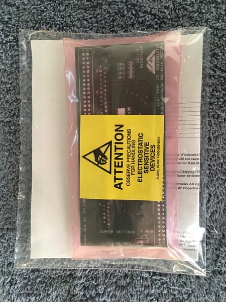
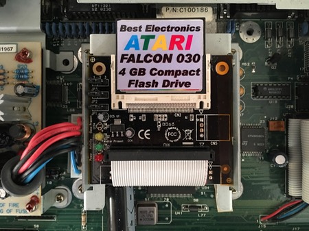
My new Falcon arrived, and the things I ordered from Best Electonics for the US conversion and upgrades arrived on the same day. I had a lot of fun setting it up. First I replaced the power supply with a US power supply, then I installed a Compact Flash IDE adapter and 4 GB compact flash (this is a kit from Best, as you can see). I also installed a Wizztronics 14 MB RAM upgrade (16 MB SIMM also came from Best).
The real-time clock battery was, of course dead, so the next evening unsoldered that and added a socket and a new RTC (Dallas 12887). I was afraid that it might not fit under the shielding (see this article), but my socket was low-profile enough so that it fit just fine. My method was to melt the solder on one row of pins in order to raise up the clock chip a bit. I then cut the pins on that side. I gently bent the other side by moving the chip back and forth until the chip was free. I used a desolder pump to clear all the holes. This was a bit difficult and time consuming because I think my pump is wearing out. It always pays to have the best tools for doing this kind of work! With a lot of persistence, I got the board all cleaned up and the socket soldered in. I added the chip, and bit my tongue while I waited for the Falcon to boot. All was well, and it booted up on the first try, and the clock is holding time perfectly.
I realized that I probably won’t be able to run Cubase with the Compact Flash drive, because the version of HDDriver needed to run Cubase is 7.93. Cubase doesn’t obey all the SCSI “rules” so it will not work with newer versions of HDDriver. I don’t believe that 7.93 supports Compact Flash adaptors, but I tried it anyway and it “bricked” my Compact Flash. No matter what version of HDDriver or AHDI I tried, the Compact Flash was no longer recognized. I tried the ICD PRO driver, and it recognized the drive and I was able to re-partition, but it only recognized 2 GB of the 4 GB, so I used HDDriver to re-partition again, and everthing was back to normal.
The next day I looked on Amazon for an a 2.5” IDE drive, and found a brand new Seagate 5400 rpm drive for $25.00. I installed this drive and set it up with several 1 GB partitions for TOS and used the rest of the drive for a LNX partition for a later installation of Mint, and a large F32 partition.
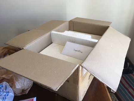
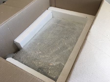
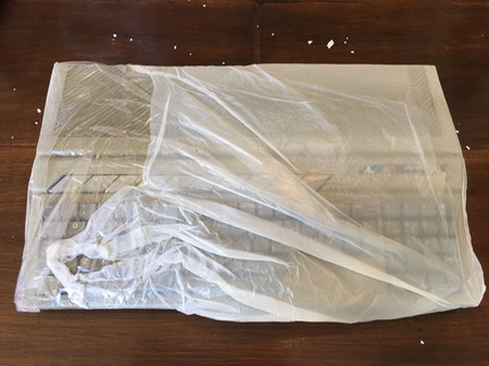
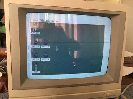
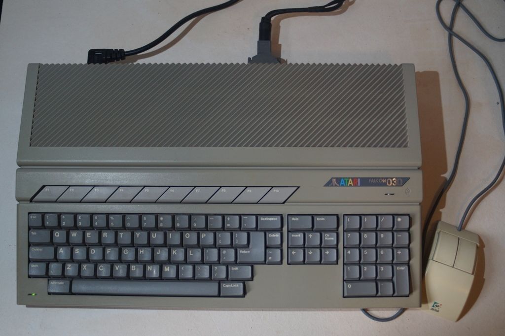
Here are some “unboxing” photos, together with photos I took of the Falcon while I did the upgrades. I also included a video of the first boot.


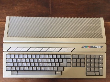
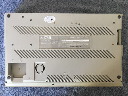


New “Stock" Falcon on the Way!
I have owned my Falcon for probably 14 years or more, and it is highly upgraded. I have always lived in fear that it will “die”, and I do not have a spare. It is the heart of my little studio, and everything revolves around it. Of course, without replacing the capacitors, all computers of this age are at risk, and it is possible that two machines will have the same shelf life.
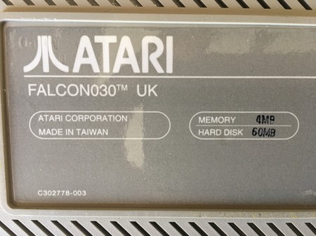
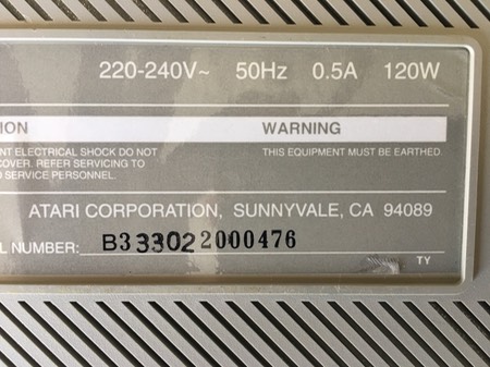
I recently decided that my last major purchase for the foreseeable future would be a second Falcon030. The computer that I bid on and won is a UK falcon, so I will be putting in a US power supply, adding 14 MB of RAM and a 4 GB compact flash IDE “hard drive.” I’m buying those things at Best Electronics.
It will be nice to have a spare “stock” Falcon for demos and games and such that is not all tied in to my studio equipment. Hopefully both computers will never “die” at the same time, and I will be still be able to repair them myself or find someone to make the repairs! Working with this vintage stuff is always an adventure!
Alesis AI-1 and switch box for MINI MACMAN (LONG)
Last night I tried an idea of adding an A-B serial switch for the MINI MACMAN MIDI interface. I was hoping that I could put the MINI MACMAN on the “A” side of the switch, and switch if off on the “B” side (nothing plugged on the “B” side) so that I don’t have to unplug and re-plug the cable all the time. Unfortunately, even though the MINI MACMAN power LED was lit, the interface did not output any MIDI messages. There may be lines on the serial switch I bought that are not implemented or something like that. I’m sure it was designed for printers or networking. I haven’t opened it or researched the issue.
I also hooked up my new Alesis AI-1 digital interface and sample rate converter. What I like about this box is that it allows me to use the D/A converters on the ADAT XT for input into my Falcon Digital Interface. It is switchable to use two tracks of the ADAT XT at a time, and convert the ADAT digital optical output to SPDIF for the Falcon Digital Interface. I still need to work with this quite a bit to see if it will provide what I really want. The concept is great, but from first testing I may have some issues.
With the ART D/IO I was using, there was a gain boost knob, which was a great feature. It seems that the signal being sent to the FDI always has to be quite “hot” for a proper recording level. Even though I was boosting the signal coming from my mixer with the ART D/IO, the sound was still very clean without white noise. With the AI-1 and the ADAT XT, there is no way to boost the signal in this way. I will probably have to run the mixer too “hot”, which may result in some noise.
I still have a lot of testing to do. I have always found that setting levels in Cubase Audio Falcon is very difficult. Without a lot of work, the final levels always come out way too low. If you are using the analog inputs of the Falcon, there are level meters you can reference, but this is not implemented for the FDI. You have to set the levels on your mixer, keyboards, etc, and hope that you are getting a nice, clean, strong level into the FDI, and Cubase. There may be some things for me to learn to work these issues out.
The other thing that bothers me is that I’m not completely sure how Cubase is handling stereo input. You have the option to record to the left or right channel of the FDI, but I don’t understand if there are two inputs on the left and two on the right so that you can record a stereo file from a stereo input. The Cubase manual is very hard to understand, and I end up doing everything mostly by trial and error.
I think things were working properly with the D/IO, but on the first try with the ADAT, the left channel was weak, and it sounded like both channels were being recorded to left and right and not separated properly.
Anyway, the concept of the AI-1 is exactly what I was looking for. I want to be able to record multichannel to the ADAT XT, and then bounce two channels at a time into the Falcon/Cubase.
I still have a lot of experimentation and research to do! I’m sure I will get it worked out.
ADAT XT Sync - Fully Operational with ACI Driver
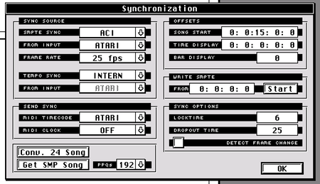
I discovered (thanks to help from friends on Atari-Forum) that there is an ACI.DRV in the MROS directory of Cubase Audio Falcon. I assume that this stands for ADAT Control Interface??
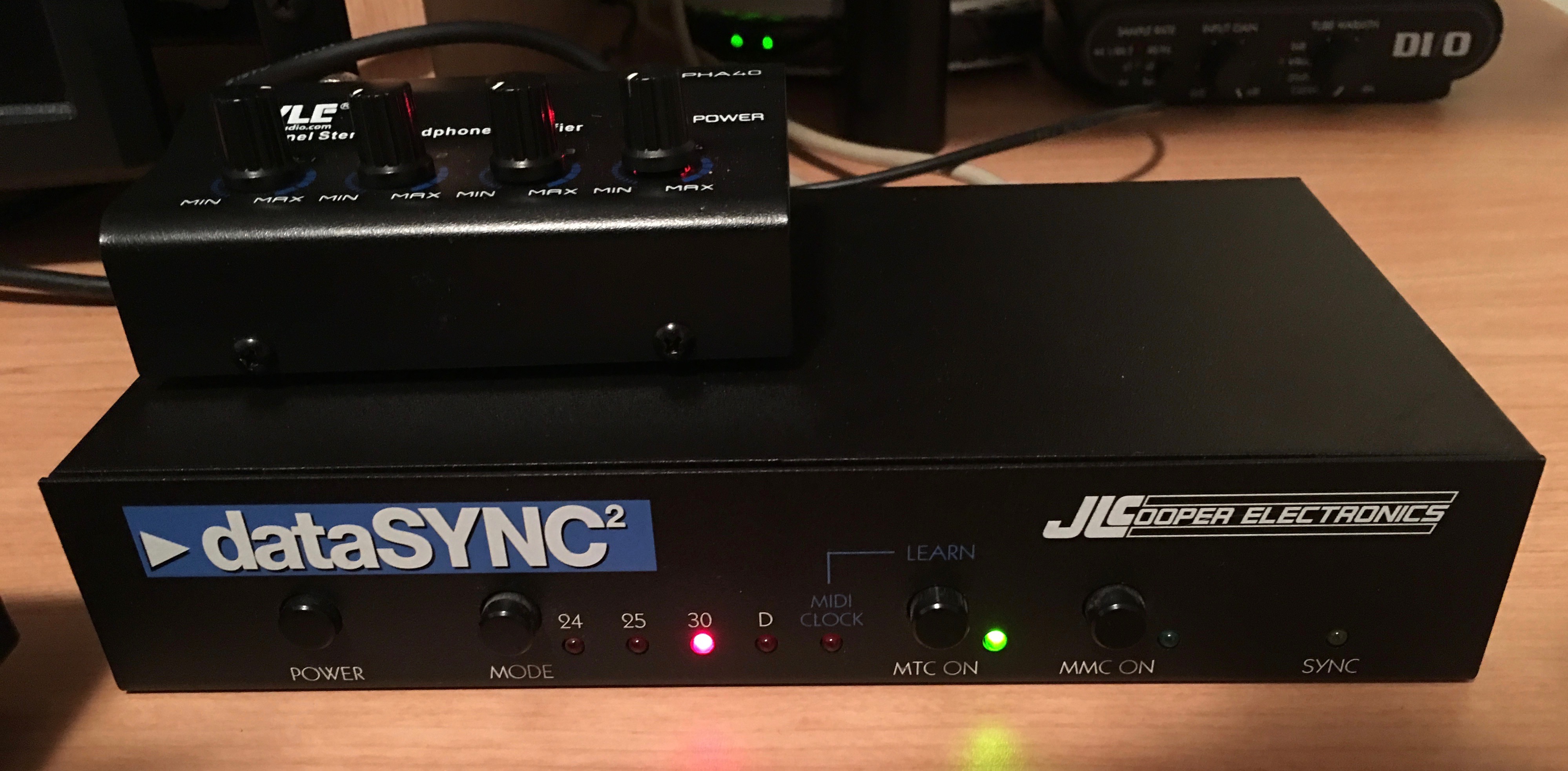
With the ACI driver and the JLCooper Datasync2, the Cubase transports now control all of the functions of the ADAT XT.
When you select a tape track in Cubase, it even record-enables that track on the ADAT XT.
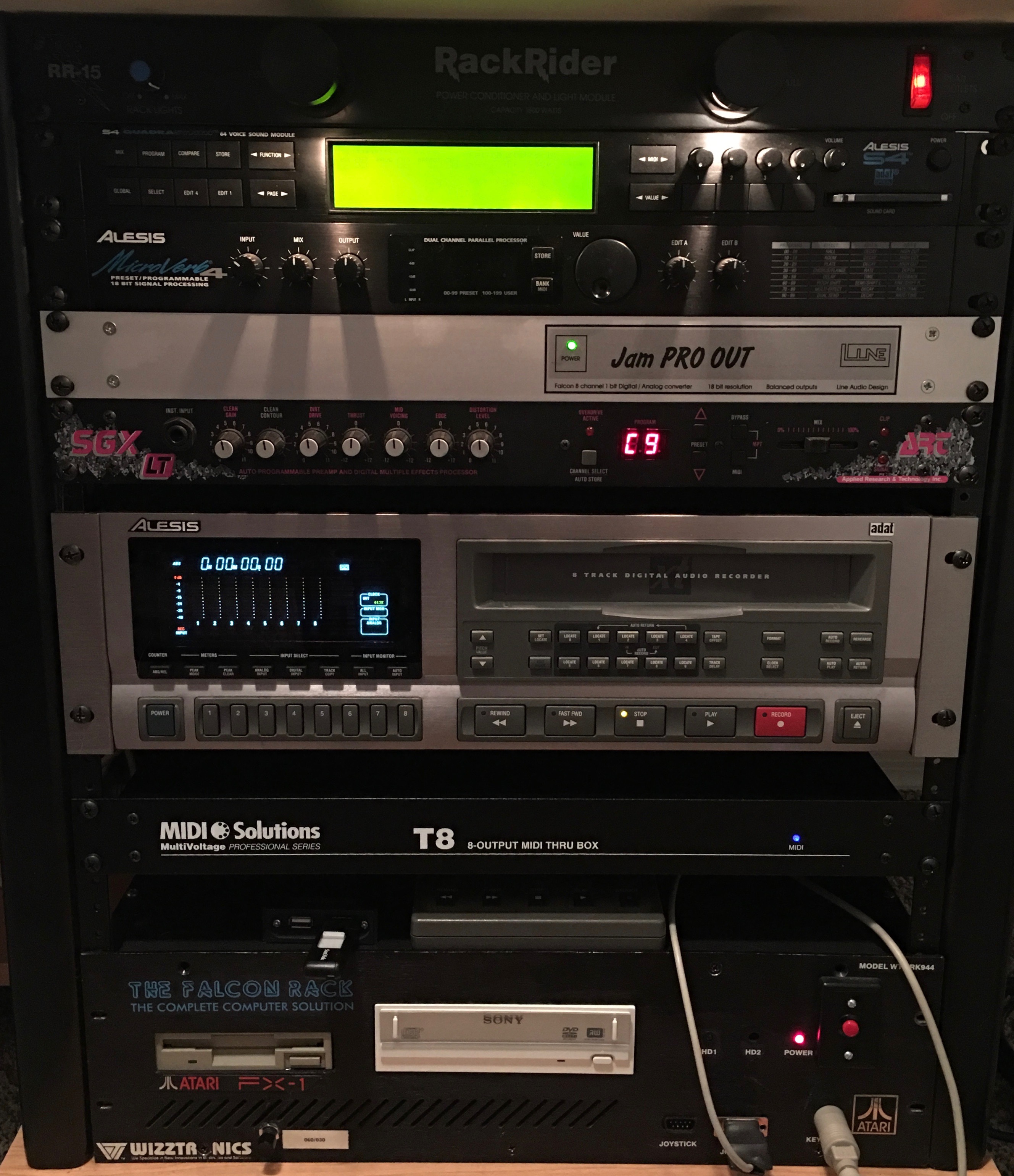
Here is the right side rack of my studio desk with the ADAT XT and MIDI SOLUTIONS T8 Thru box installed. No more room!
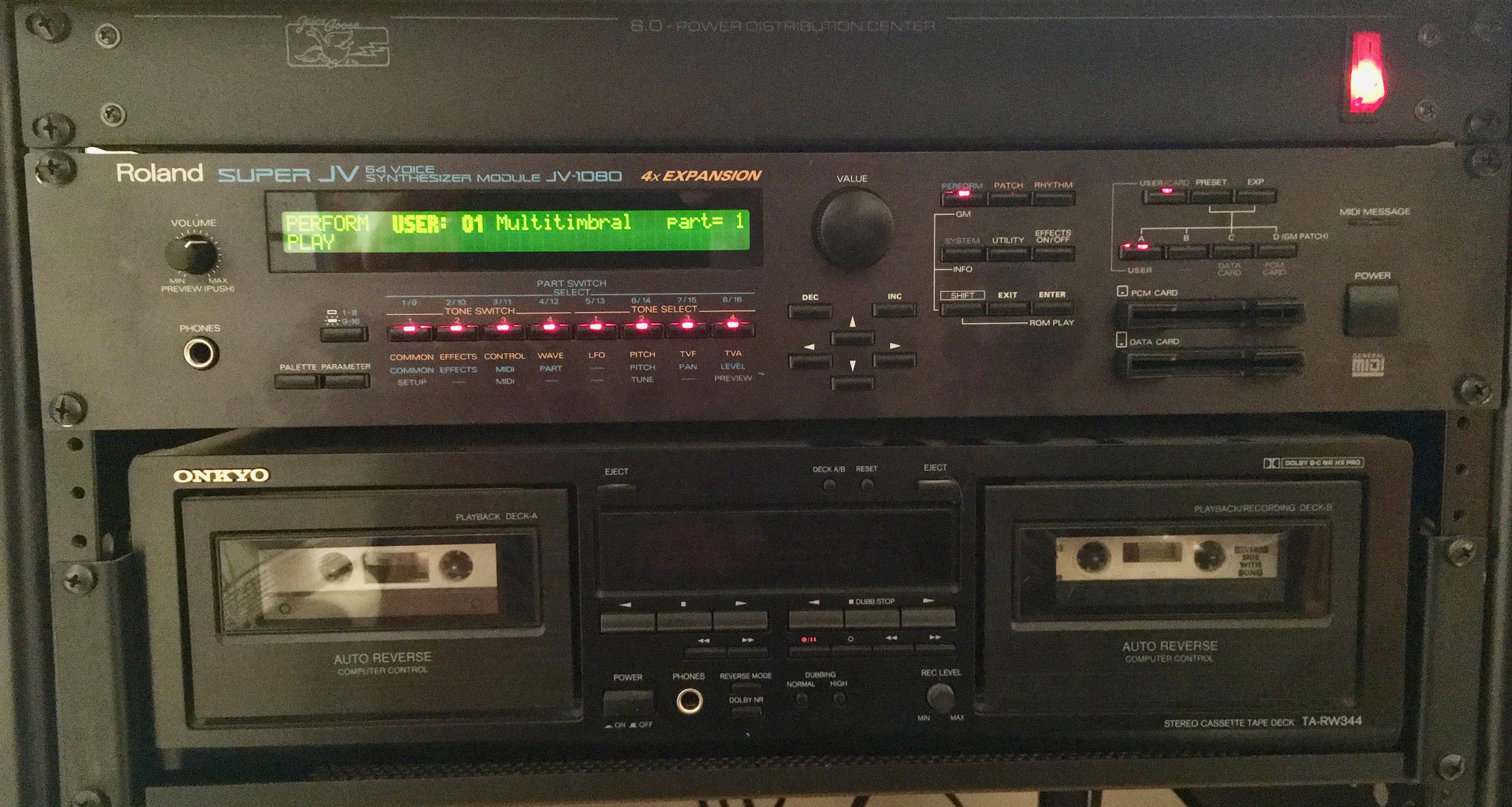
Here the left side rack of my studio desk with the JV-1080 installed:
Here is the JLCooper DataSync2. The little box on top is just my headphone amp.
Once my Alesis AI-1 arrives, this project will be completed. I’ll probably remove the ART SGX-LT guitar processor, and put the AI-1 above the ADAT XT.
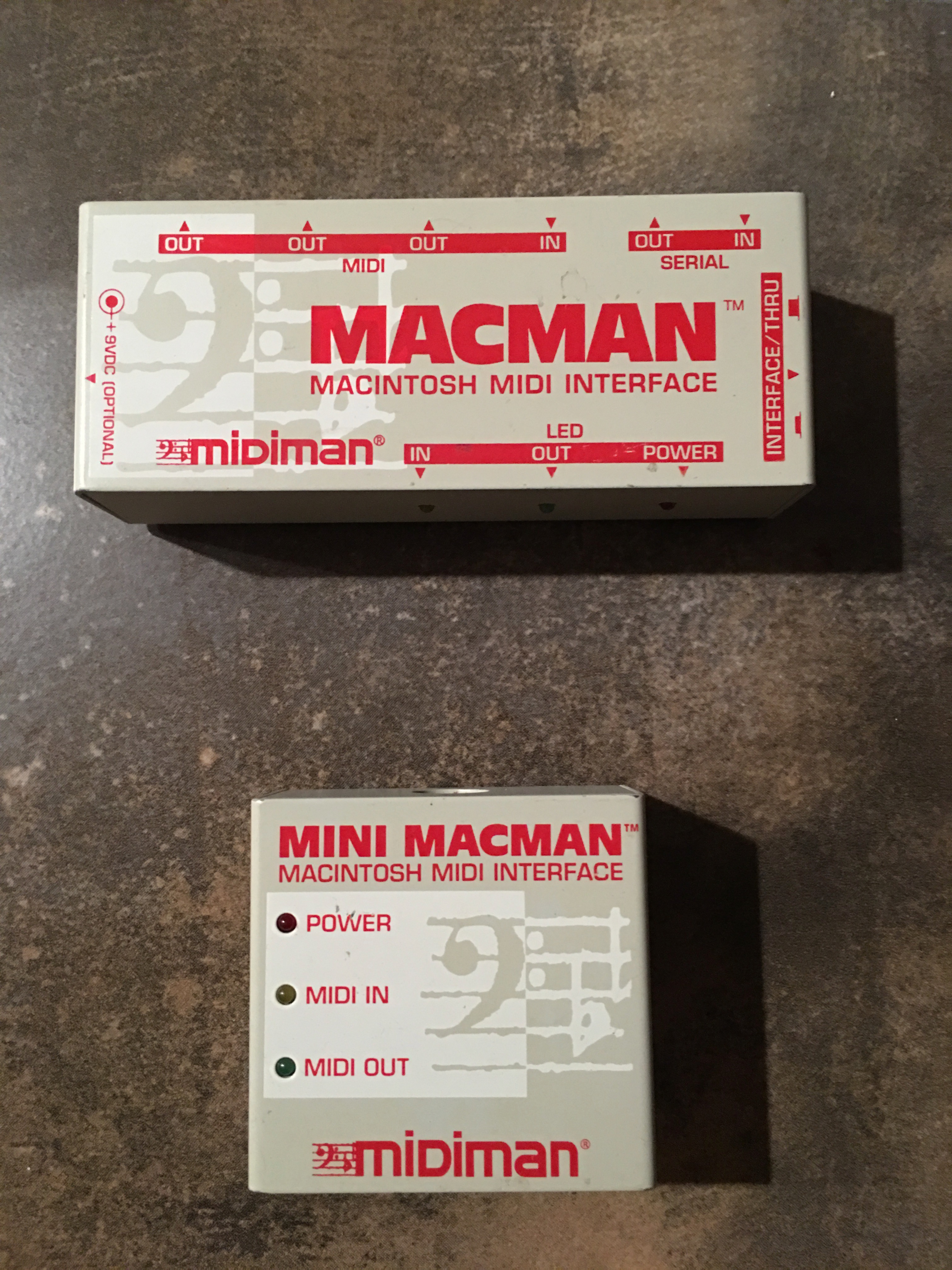
midiman MACMAN AND MINI MACMAN
I was in desperate need of an additional midi OUT so that when my JV-1080 arrives, I can have another 16 midi channels to send to it. I have not been able to find any of the Soundpool, Steinberg or other midi interfaces, but I was able to find a midman MACMAN and a MINI MACMAN.
These interfaces hook to the the LAN port on the Falcon. It is very important that the LANPORT.DRV is in the MROS directory, AND THAT YOU DO NOT HOOK UP THE SERIAL CABLE UNTIL CUBASE HAS LOADED. If you have the serial cable hooked up when you boot the computer you will get a blank screen. If you have the cable hooked up before you run cubase, the mouse cursor will lock up. READ LAN****.TXT in the MROS folder.
I seem to remember reading something about the timing not being as tight with these interfaces, but I have verified that they are working. I think that only one out is supported by Cubase. The other two on the larger interface may function as a THRU, but in Cubase you only have the option for the ATARI midi out (Falcon) or the LANPORT midi out (Macman interface), not multiple outs on the LANPORT. I bought both of the interfaces out of curiousity because they were very inexpensive, but I think I’ll be using the MINI MACMAN, since it looks to me that just the one out is supported anyway.
UPDATE - I have a serial switch for the old Apple-type serial cables on the way so that I can just operate the switch to connect the MINI MACMAN instead of always plugging and unplugging the Lan Port serial cable.